Immersive Compass · Implementation

From your site to 3D wayfinding

Turn your site into an easy-to-understand 3D map. With Compass, visitors locate services, find shops and reach their destination.

Getting started

A project built step by step

Let’s start with a concrete example: a railway station, its spaces and the destinations passengers need to find.

  1. The starting point

    Define the spaces and wayfinding needs

    Before modelling, identify the areas to cover, the people to guide and the destinations to highlight. The aim is to help everyone understand the site and find what they need.

    At this station, the scope includes the forecourt, main concourse, two platforms and shopping area. The first points of interest are the information desk, toilets, McDonald’s, PAUL and Amazon lockers.

    Result: An agreed scope and an initial list of destinations, addressing practical needs: reaching a platform, finding a service or visiting a shop.

    Details: defining the project

    Identify the spaces open to the public, entrances and access points to destinations. Specify point-of-interest names and categories, accessibility requirements, and information to confirm with the site operator and retailers. This scope will guide the plans, 3D model and wayfinding.

    Photorealistic view of a station with a glazed concourse, two platforms and tracks extending into the background, McDonald’s and PAUL shops, an information desk, Amazon lockers and toilets.
    The site to represent: a railway station, its platforms, services and shops. Illustration of a fictional site.
  2. The site documents

    Gather plans and site surveys

    Collect the available station plans, dimensions and photographs. Identify the concourse, platforms, shops, services and their entrances: these documents provide the references needed to prepare an accurate 3D replica.

    Result: A consistent set of documents for modelling the site and locating its points of interest.

    Details: preparing the source information

    Check the plans’ date, scale and consistency with the actual site. Record missing dimensions, openings, platform access and any changes in level. Add photographs and confirm shop boundaries, public entrances and permitted access with the site operator. Keep these references for modelling and preparing routes.

    White-line blueprint of the same station on a blue grid: shops on the left, central concourse, information desk and toilets on the right, forecourt below and two platforms at the rear.
    Plans provide a shared basis for understanding the site layout. Illustration of the station as a blueprint.
  3. The digital replica

    Model your site in 3D

    Forge

    Build the volumes, openings and objects needed for wayfinding from the plans. The station takes shape progressively, keeping the shops, concourse, services, forecourt and platforms consistent with the site.

    Result: A clear 3D model, ready for points of interest and routing.

    Details: preparing the model in Forge

    Preserve scale, space boundaries and entrance positions. Use simple geometry and solid-colour materials for clarity. Check openings and circulation areas against the site documents before preparing the routing graph.

    Station blueprint with some walls and furniture already modelled in 3D.
    Modelling progresses over the plan, preserving proportions and positions.
  4. Points of interest

    Link each point of interest to its 3D object

    Forge

    The model is complete. Link shops and services to their 3D objects with a name, category and logo or pictogram. Travellers can then identify the toilets, information desk, luggage lockers, McDonald’s and PAUL.

    POIs are organised at three levels: a hierarchy of categories, services or brands, and their instances at specific locations. The “McDonald’s” service can group several restaurants; its instance at this station is the one linked to the 3D object.

    Result: Identified destinations positioned in the model, ready to be linked to the routing network.

    Details: organising destinations

    Check each POI’s name, category and associated 3D object. Images and logos appear in the callouts; the model retains solid-colour materials. In the next step, linking a waypoint defines the access point used to calculate a route.

    Categories have parent/child relationships: Food → Dining → Fast food. The “McDonald’s” service belongs to the last category; the “McDonald’s at Raincourt station” instance represents the local restaurant. Similarly, the “Toilets” service, under “Personal services”, can have an “Outdoor toilets” instance. Each instance retains its location, 3D object and access point, while the service carries the shared identity.

    Scroll the plan horizontally to explore the model and its markers.

    • McDonald’s
    • PAUL
    • Information
    • Lockers
    • Toilets
    Each callout identifies a point of interest and links it to its representation in the digital replica.
  5. Routing

    Build the routing network

    Forge

    Map the available passages on the model and connect them with waypoints. Each POI is linked to an access waypoint, enabling route calculation to reach the destination while respecting travel directions and constraints assigned to the segments.

    Adding metadata to the routing network adapts routes to each visitor’s requirements. A reduced-mobility profile avoids stairs and uses accessible passages. If no compatible route reaches the destination, the visitor is directed to reception for assistance.

    Result: A routing graph linked to destinations, with explicit rules for choosing permitted passages.

    Details: waypoints, links and rules

    In Forge, green circles represent waypoints and green segments represent graph connections. Dragging a POI onto a waypoint links the destination to that network point. Place waypoints at entrances, junctions and changes of direction, following passages that can actually be used.

    Rules belong to the segments: one-way travel, maximum weight, maximum width or a required security badge. A one-way segment is red with an arrow; other constraints remain attached to green segments. Route calculation needs travel-profile data to evaluate these conditions. The examples below are illustrative and must be adapted and checked on site.

    Describe stairs, lifts, ramps, passage widths and access conditions on the relevant graph elements, then evaluate that metadata against the user profile. Define a fallback destination: the route to reception must also be accessible; otherwise, provide a way to contact reception. Test these cases against actual site conditions.

    Scroll the plan horizontally to explore the model and its markers.

    • McDonald’s
    • PAUL
    • Information
    • Lockers
    • Toilets
    Example network on the same model. Markers 1–4 refer to the rules below; the layout must be checked against the site’s actual entrances.
    • Routing segment
    • Waypoint
    • One-way
    • POI / waypoint link

    From the POI to its access point. In Forge, drag a POI onto a green circle to link the destination to a waypoint. The dashed blue lines illustrate that association here. The green network represents the passages available to route calculation.

    1. One-way travel

      The passage may only be used in the direction of the red arrow.

    2. Maximum weight: 100 kg

      A profile exceeding this limit must use another passage.

    3. Maximum width: 3 m

      The declared width must meet the limit set for this segment.

    4. Security badge required

      The passage is reserved for profiles with the relevant authorisation.

  6. Commissioning

    Position kiosks and test the guidance

    Forge · Compass

    Each wayfinding kiosk is represented by a Device placed in the model at its actual location, in front of a network waypoint. This point becomes the starting point for guidance: visitors select a destination on the kiosk screen and see how to get there.

    Result: A kiosk located within the site, with routes checked from that starting point to the POIs.

    Details: from Device to visitor route

    Position and orient each Device to match the installed kiosk. Check the starting waypoint in the network and the continuity of segments to the POI access points. Routes must follow walkable passages and respect the travel and access rules defined in the previous step.

    On the kiosk, test destination selection, the start of the route and the clarity of first-person directions. Then walk the route to check the initial steps, changes of direction and arrival. This example connects the forecourt kiosk to PAUL.

    In the model: place the Device

    The Device represents the installed kiosk. The waypoint in front of its screen locates the visitor’s starting point on the routing network.

    On the kiosk: get to PAUL

    Illustration of a Compass kiosk screen with a first-person view of the station and an arrowed route to PAUL.
    From this kiosk, the first-person view shows the direction to follow and the landmarks to recognise on the way to PAUL. Illustrative guidance interface.
  7. Going further

    Connect guidance and keep the site up to date

    Compass · Beholder · Hub

    Once the model and routes are ready, several workstreams can extend the project. Depending on the needs, this shared foundation can support real-time guidance, printed materials, external applications and the site operator’s administration tools.

    Result: Reusable mapping, routes adapted to on-site conditions and content that teams can maintain across their site.

    Use the live status of equipment

    Connecting Compass to Beholder and the Hub provides real-time equipment status. A lift that has broken down or is under maintenance must no longer appear in a route: guidance looks for another option compatible with the visitor’s profile, or directs them to reception.

    Real-time statusBeholder + Hub
    LiftUnder maintenance · passage excluded
    Route adaptationAnother accessible route, or reception
    Implementation details

    Link each piece of equipment to the graph passages that depend on it. The integration must define how “available”, “broken down” and “under maintenance” states affect routing, and what happens when information is no longer current. Check alternative routes and the fallback to reception.
    Include traffic and waiting times

    Connecting the network to systems that measure traffic or waiting times at a point on the site refines the estimated journey time. Time spent waiting at a security gate can be added to the overall travel time.

    Illustrative example

    3 minTravel
    5 minWaiting at security
    Estimated total time8 min
    Implementation details

    Attach traffic or waiting-time data to the relevant passage point, then include that duration in the route cost. Define the update frequency and a fallback estimate when a measurement is missing. The diagram’s values illustrate the calculation; they are not measurements from the site.

    Produce printable maps

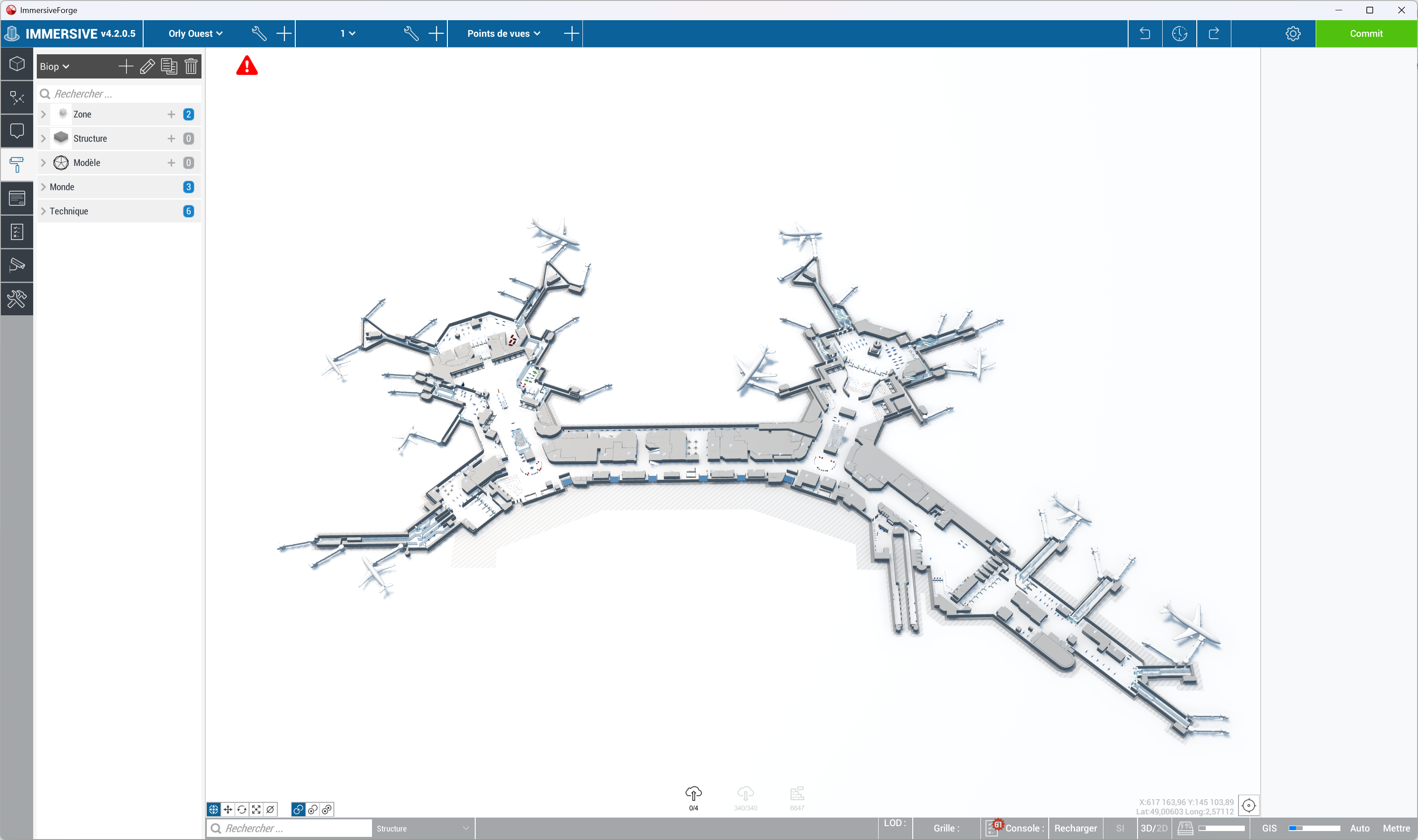
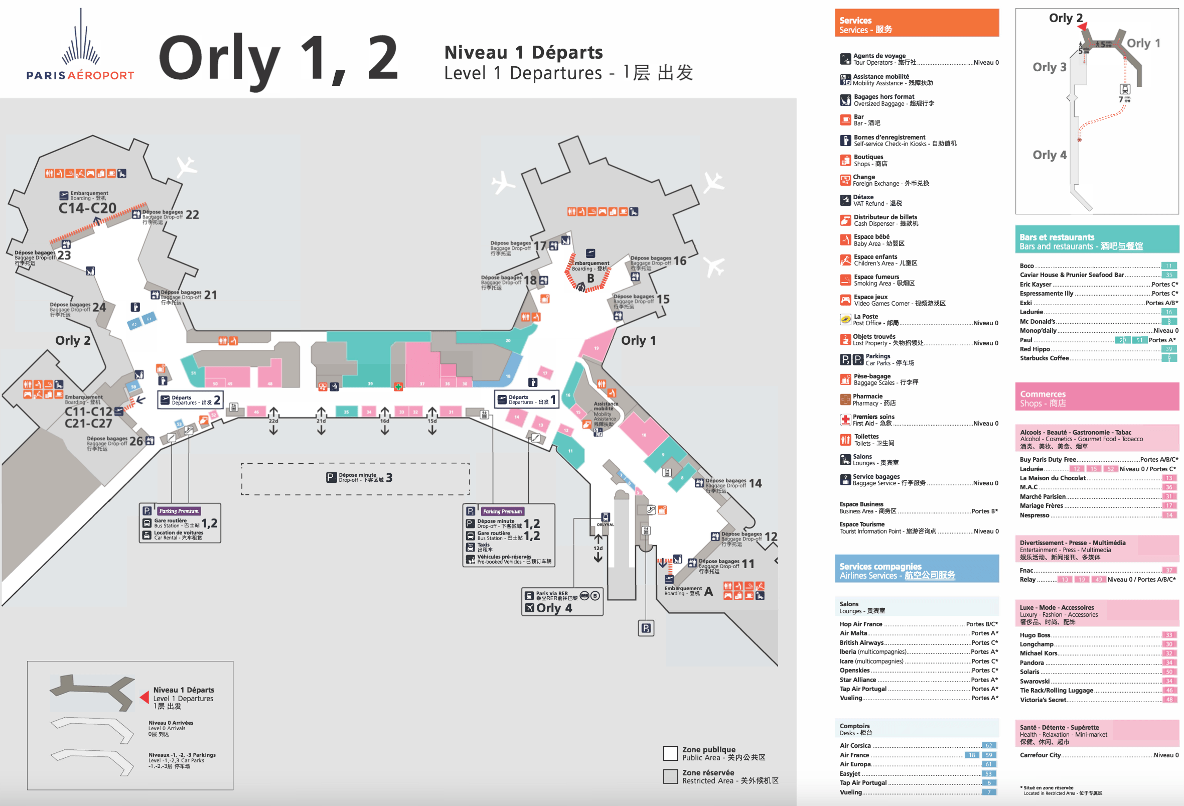
    Mapping can also support printed materials. Tools outside Forge can prepare printable maps from Immersive data, styled for the site with levels, shops, services, landmarks and a legend. Orly illustrates the transition from the model to a map for visitors.

    Orly Ouest model in Immersive Forge, showing the terminals and piers.
    Orly: the model in Forge.
    Printable map of Orly 1 and 2, Level 1 Departures, with shops, services and a legend.
    Orly: a visitor map with its legend and landmarks.
    Implementation details

    Prepare the 2D view and select the levels and information to publish. Apply the site’s visual identity, arrange labels and the legend, then check legibility at the chosen print size. The screenshots show both types of representation; layout is handled by the map-production tools.

    Supply mapping to external applications

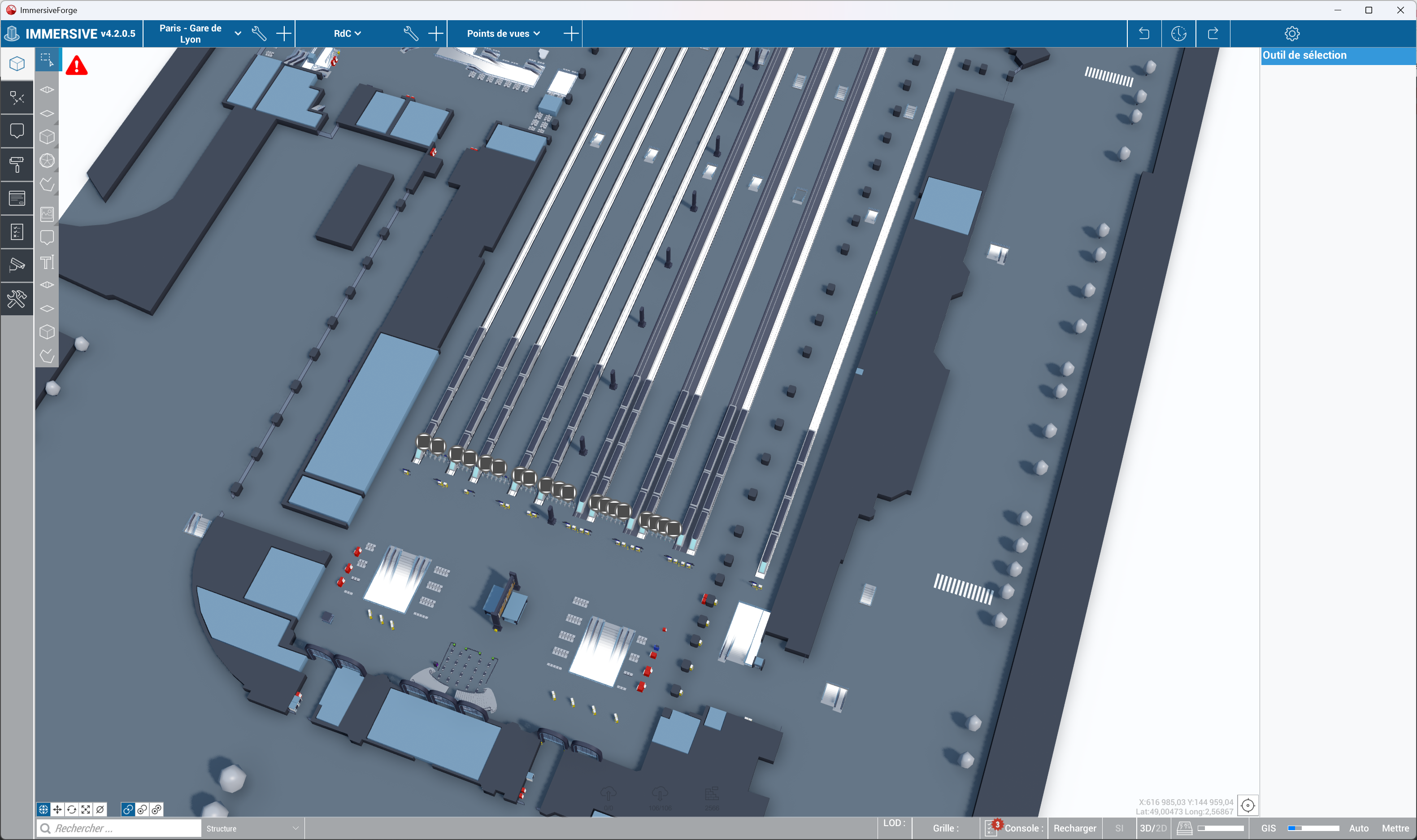
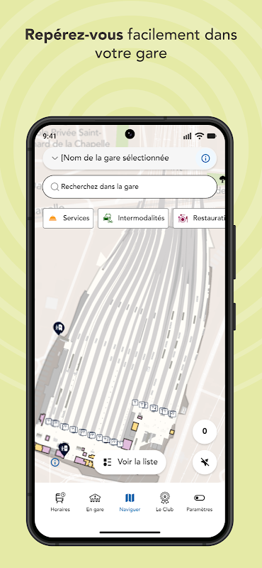
    Prepare the API interfaces and exports required by the client’s applications: GeoJSON, Web APIs or other expected formats. Mapping and POIs become reusable in external interfaces, as illustrated by Gare de Lyon’s Forge model and its representation in the “En gare” application.

    Paris-Gare de Lyon model in Immersive Forge, showing the hall and tracks.
    Gare de Lyon: mapping prepared in Forge.
    Example of Gare de Lyon mapping in the En gare mobile application, with search and service categories.
    Reuse in the “En gare” application.
    Implementation details

    Agree with the consuming application on the geometries, coordinate system, levels, identifiers and POI properties to expose. Define access rights and how often updates are published. Interfaces and transformations must match each application’s expected contract.

    Give operators the tools to administer their site

    A shopping centre, station or airport needs to keep its directory up to date. Administration tools can be provided to the client to manage categories, services and their instances, update brands and maintain information for each location across the site.

    1. Categories · parent / childFood → Dining → Fast food
    2. Service or brandMcDonald’s
    3. Instance at the siteMcDonald’s at Raincourt station
    1. Categories · parent / childPersonal services
    2. Service or brandToilets
    3. Instance at the siteOutdoor toilets
    Implementation details

    Separate shared service information — identity, logo and category — from instance information, such as local name, opening hours, location, 3D object and access waypoint. Define team permissions and management scope, then organise validation and publication of changes to kiosks, applications and future printed maps.